 |
Pressure Regulating Valves ( Downstream ) Transmitter SERIES - MIC - 711 |
Manufacturer, Exporter, Wholesaler and Supplier of Automation and Instrumentation Products such as Pressure Regulating Valves Transmitter, Downstream Pressure Regulating Valves and our setup is situated in Pune, Maharashtra, India. |
INTRODUCTION
Downstream Pressure regulating valve is self contained, self Operated control devices, maintain a desired reduced outlet pressure, while providing the required fluid flow to satisfy a variable downstream demand. The valve at which the reduced pressure is maintained is the outlet pressure setting of the regulator. It utilizes energy from the controlled system. The pressure reducing regulators are manufactured in a variety to manage downstream system pressures in low, medium, high flow applications; model features a diaphragm /piston type or combination of both to suit different applications.
|
|
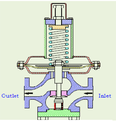
| DIRECT OPERATED VALVE- MIC-721 |
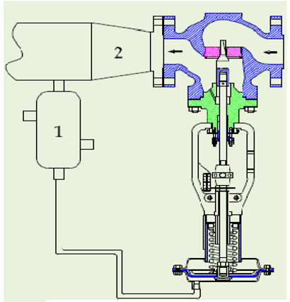
STEAM PRV WITH CONDENSATE
CHAMBER MIC- 731 |
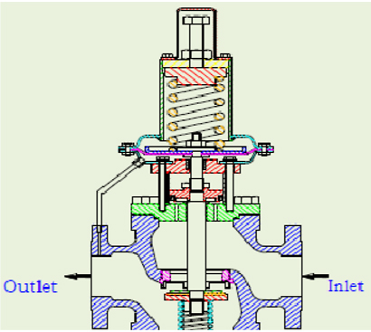
DIRECT OPERATED BALANCE
DESIGN VALVE-MIC- 741 |
 |
 |
 |
|
|
FEATURES :
- Reduces higher inlet pressure to a constant lower Outlet
pressure.
- Outlet pressure is accurate over wide range of flow.
- Pilot-operated main valve is not subject to pressure fall off
Characteristic of direct-acting PRV’s.
- Outlet pressure is adjustable over complete range of control spring.
|
|
PRINCIPLE OF OPERATION :
|
All type of regulators generally fit into one of the following two basic categories.
1) Direct Operated
2) Pilot Operated
The specific considerations peculiar to your control needs is to be carefully studied and understood
to determine which method of control is the better choice. Regulators when compared to control
Valve / Instrument package have their advantages and limitations.
Table No.2 lists selected characteristic of both. |
| |
The operational principal of both types of regulators is explained as follows.
A) DIRECT OPERATED |
| |
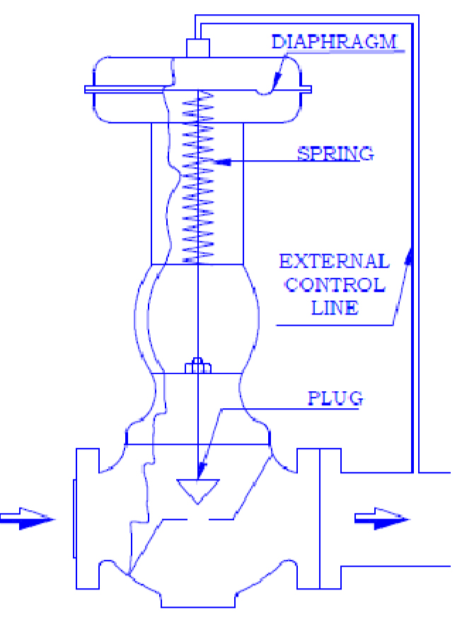
In operation, a direct-operated, pressure reducing regulator senses the
downstream pressure through either internal pressure registration or an external control line. This downstream pressure opposes a spring which moves the diaphragm and valve plug to change the size of the flow path through the regulator. Characteristically direct operator
regulator are adequate for narrow-range control, and where the allowable change in output pressure can be 10 to 20% of the outlet
pressure setting. This 10 to 20% is typical although finer control can be achieved depending on the specific application requirement.
 |
 |
| |
|
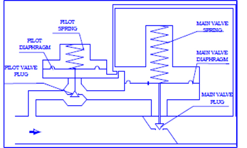
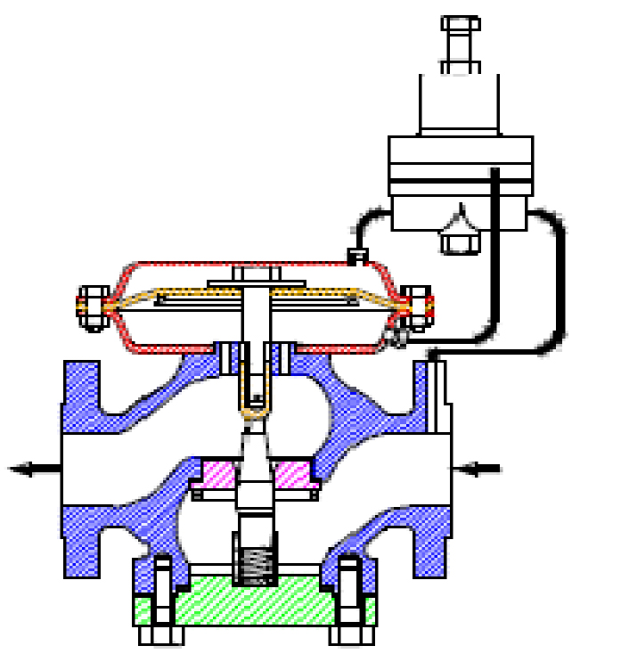
A pilot-operated system uses a two-path control. In two path control,the main valve diaphragm responds quickly to downstream pressure changes, causing an immediate correction in the main valve position. At the same time, the pilot diaphragm diverts some of the reduced inlet pressure to the other side of the valve diaphragm, which controls the final positioning of the main valve plug.Two-path controls result in fast response. Pilot-operated regulators are preferred fo broad range control, or where the allowable change in outlet pressure is required to be less than 10 percent of the outlet
pressure setting. They are also commonly used when remote set point adjustment is required for a regulator application. |
|
 |
|
| |
|
|

|
| |
DESIGN FEATURES :
- Operates automatically off line pressure.
- Heavy-duty, nylon-reinforced diaphragm.
- Round-shaped, soft seat seal provides drip-tight class VI closure.
- Diaphragm assembly guided top and bottom.
- Throttling seat retainer for flow and pressure stability.
- Easily maintained without removal from the line.
- Pressure adjustment by single adjusting screw.
- Replaceable seat ring.
- Range of body & diaphragm material combinations to meet majority of requirements.
- IBR certification in Form III C available.
- Designed ruggedly to withstand shocks.
- Simple and economic design.
|
QUALITY AND PERFORMANCE GUARANTEE :
- Produced with Quality Systems accredited to ISO 9001: 2008 by Bureau Veritas.
- Full material certification available for all major component Parts.
- Full guarantee on design and Performance.
- All testing performed to the requirements of ANSI B16.34.
|
VALVE SIZING CO-EFFICIENT Cv RATING. (Table 1)
| VALVE SIZE |
Inch |
1/2 |
3/4 |
1 |
1 1/2 |
2 |
3 |
4 |
6 |
8 |
10 |
12 |
|
mm |
15 |
20 |
25 |
40 |
50 |
80 |
100 |
150 |
200 |
250 |
300 |
Pressure
Deviation
(Kg/cm²) |
0.3 |
0.7 |
0.3 |
0.7 |
0.3 |
0.7 |
0.3 |
0.7 |
0.3 |
0.7 |
1.7 |
1.7 |
2.0 |
2.0 |
2.5 |
2.5 |
Cv Value |
2 |
4 |
4 |
5 |
5 |
9 |
12 |
12 |
18 |
15 |
50 |
80 |
200 |
300 |
450 |
650 |
|
REGULATOR vs. CONTROL VALVE WITH INSTRUMENTION (Table 2)
| Selected Regulator Characteristic |
Selected Control Valve/Instrument Characteristic |
|
-
Wide variety of construction material
and accessories available.
-
Transmitting and controlling
instruments are separate and may be
remote mounted.
-
Specific construction has broad
application flexibility.
-
Separate controller allows for
adjustable-band proportional control
with reset and/or rate optional for
excellent control response.
|
|
|
GUIDELINES ON OPERATION & INSTALATION :
- All regulators should be installed and used in accordance with applicable standard and localcodes and regulations.
- Adequate overpressure protection should be installed to protect the regulator from overpressure. Adequate overpressure protection should also be installed to protect all downstream equipment in the event of regulator failure.
- Downstream pressures significantly higher than the regulator's pressure setting may damage soft seats and other internal parts.
- The recommended selection for orifice diameters is the smallest orifice that will handle the flow.
- Regulator body size should never be larger than the pipe size. In many cases, the regulator body is one size smaller than the pipe size.
- When adjusting set point, the regulator should be flowing at least five percent of the normal operating flow.
- Direct-operated regulators generally have faster response to quick flow changes than pilot operated regulators.
- Droop is the reduction of outlet pressure experienced by pressure-reducing regulators as the flow rate increases. It is stated as a percent, in inches of water column (mbar) or in pounds per
square inch (bar) and indicates the difference between the outlet pressure setting made at low flow rates and the actual outlet pressure at the published maximum flow rate. Droop is also
called offset or proportional band.
- Downstream pressure always changes to some extent when inlet pressure changes.
- Most soft-seated regulators will maintain the pressure within reasonable limits down to zero flow. Therefore, a regulator sized for a high flow rate will usually have a turndown ratio
sufficient to handle pilot-light loads during off cycles.
- Diaphragms leak a small amount due to migration of gas through the diaphragm material. To allow escape of this gas, be sure casing vents (where provided) remain open.
- A disk with a cut appearance probably means you had an overpressure situation. Thus, investigate further.
- When using relief valves, be sure to remember that the reset point is lower than the start-to bubble point. To avoid seepage, keep the relief valve set point far enough above the regulator set
point.
- Vents should be pointed down to help avoid the accumulation of water condensation or other materials in the spring case.
- Make control line connections in a straight run of pipe about 10 pipe diameters downstream of any area of turbulence, such as elbows, pipe swages, or block valves.
- Do not use needle valves in control lines; use full – open valves. Needle valves can cause instability.
|
| |
| |
|
